Vertical Inline Pumps Intro to Pumps
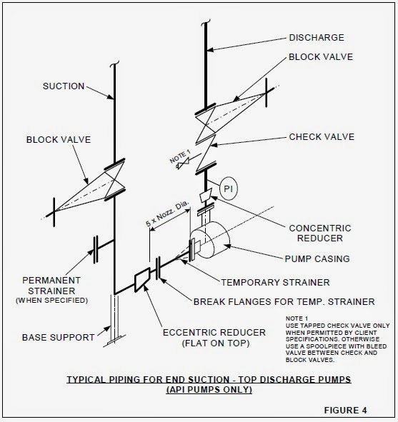
diameter between the pump inlet and any obstruction in the suction line. Obstructions include valves, elbows, "tees," etc. Keeping the pump suction piping short ensures that the inlet pressure drop is as low as possible. The straight-run pipe gives users a uniform velocity across the pipe diameter at the pump inlet. Both suction. 2
How to do Pump Piping with Layout Explained PIPING GUIDE
The pump-line-nozzle injection system is so-called for producing high fuel pressure in a pumping element, transferring the fuel pressure pulse through a high pressure injection line, and then spraying this fuel into the cylinder via the nozzle of an injector [113].

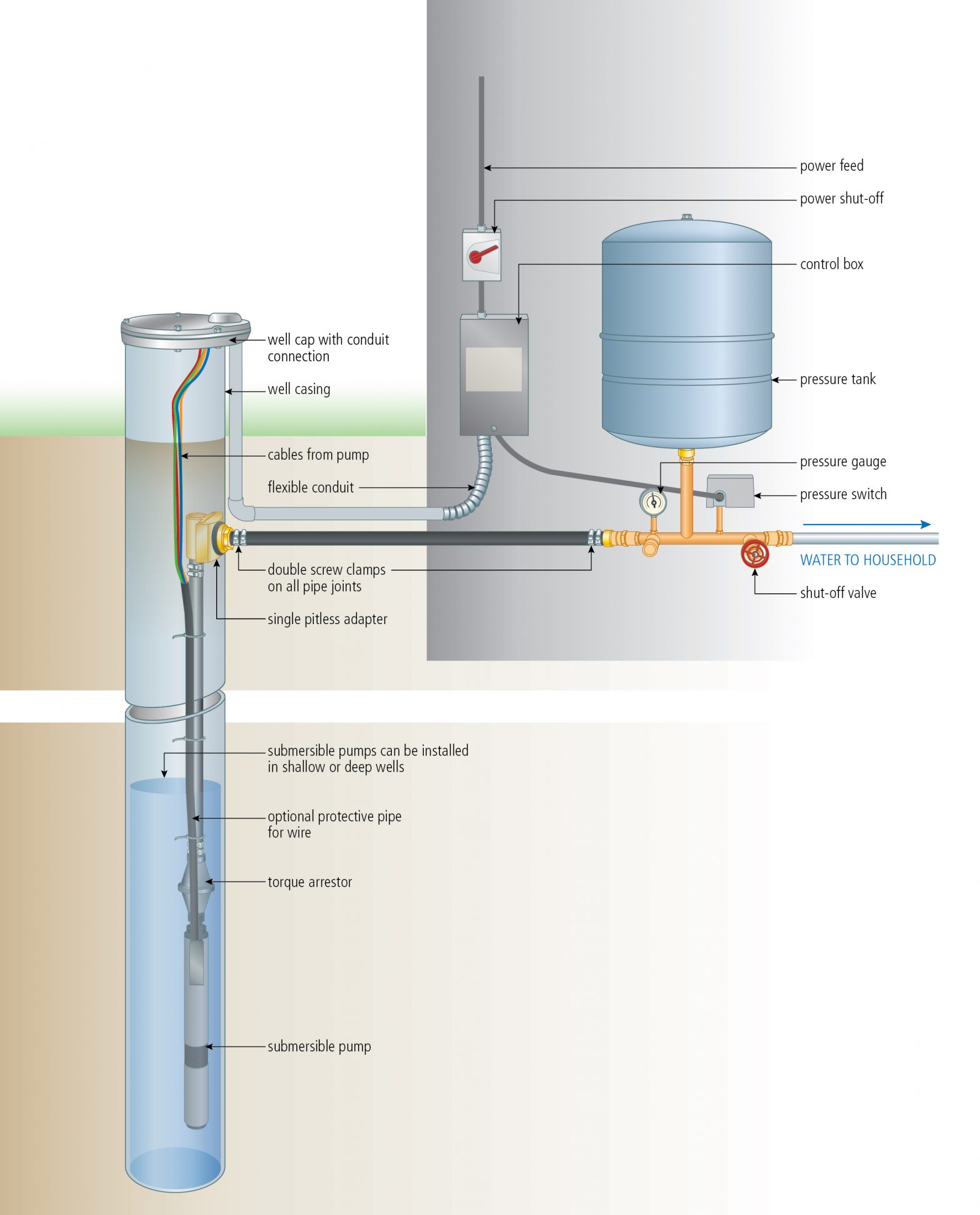
Water Booster Pump Installation Diagram
PERMCO DUMP-PUMP TWO AND THREE LINE OPERATION. In applying the Permco Dump Pump, an understanding of the 2-line and 3-line circuits is essential for proper operation and maximum unit life. In the two line operation, one line is connected from the oil tank to the inlet of the pump and one line is connected from the cylinder port of the valve to.

2003 Gmc Sierra 1500 Abs Pump Lines Diagram
By Lambda Geeks The 2 line jet pump diagram is a visual representation of a type of pump commonly used in residential and commercial applications. This pump is designed to draw water from a well or other water source and deliver it to various locations.
INSTALL A SUBMERSIBLE PUMP 6 Lessons for doing it right
Two Pump Single Heater Pool & Spa Plumbing Diagram 3 Jandy 3-Way Valves 4 Jandy Check Valves Common pool plumbing layout for two separate systems (pool and spa) sharing the same heater. Pool and Spa Combination with Ozone and Chemical Feeder 4 Jandy 3-Way Valves 1 Jandy 2-Way Valve 2 Jandy Check Valves 2 Jandy Valve Actuators
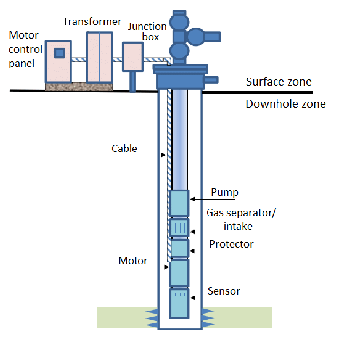
Submersiblepumpdiagram Aarohi Embedded Systems Pvt. Ltd.
ELECTRIC SINGLE LINE DIAGRAM 6"MALE CAMLOCK w/CAP (316 S.S.) INFLUENT PIPE DROP BOWL NOTES: ANCHORS TO BE CONSTRUCTED OF 316 STAINLESS STEEL "H.A.S." ROD BY HILTI OR EQUAL). THE ANCHORING SYSTEM SHALL INCLUDE ADHESIVE (HILTI H.V.U. OR EQUAL) WITH AN EMBEDMENT DEPTH OF 4 1/4". INSTALL DROP BOWL AFTER THE WET WELL LINER IS INSTALLED.
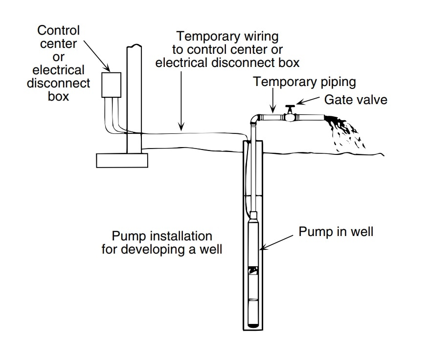
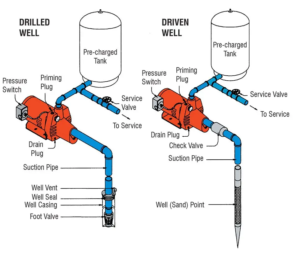
How to Install and Wire a Well Pump Well Pump Installation Guide
1 Description 2 Functions 3 Summary of Designations and Functions 4 Location 4.1 PSE Pump 4.2 Inlet Air Filter 5 Part Numbers 6 Specification Values (Obtained by Measurement) 6.1 Pressure Regulated Switch 6.2 Pressure at MKL Port 6.3 Solenoid Coil Resistance 7 Baseline Pressure Tests 8 Issues 8.1 Pump Fails to Work Due to Pneumatic Leaks
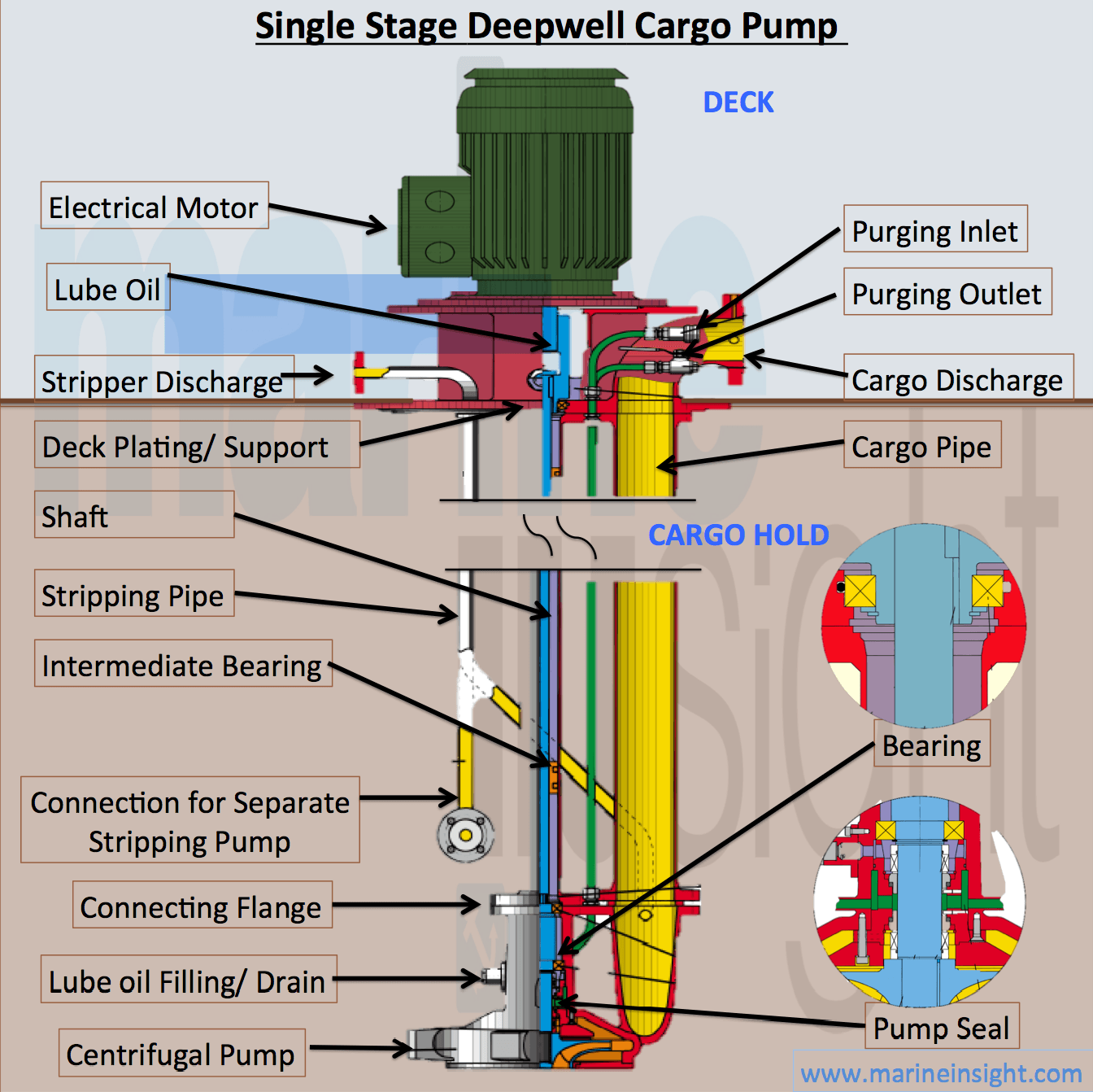
Infographics Single Stage Deepwell Cargo Pump
Both lines have 2 orifices drilled into check valves at least 5 feet apart. Jockey pump is installed on the high pressure side of the fire pump piping. Fire pump is installed on the high pressure side of the fire pump piping. A ¾" casing relief valve has been installed on the discharge side of the fire pump before the fire pump check valve.
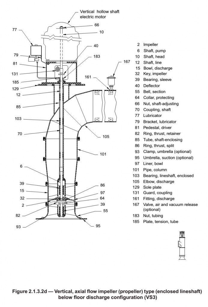
Vertical Turbine Pumps Intro to Pumps
As Gary Klein, an energy consultant and hot-water specialist, points out, "Compared to the time it takes hot water to arrive in 3⁄8-in.-dia. pipe at a given flow rate, it takes roughly 1-1⁄2 times as long in 1⁄2-in.-dia. pipe, three times as long in 3⁄4-in.-dia. pipe, and six times as long in 1-in.-dia. pipe."
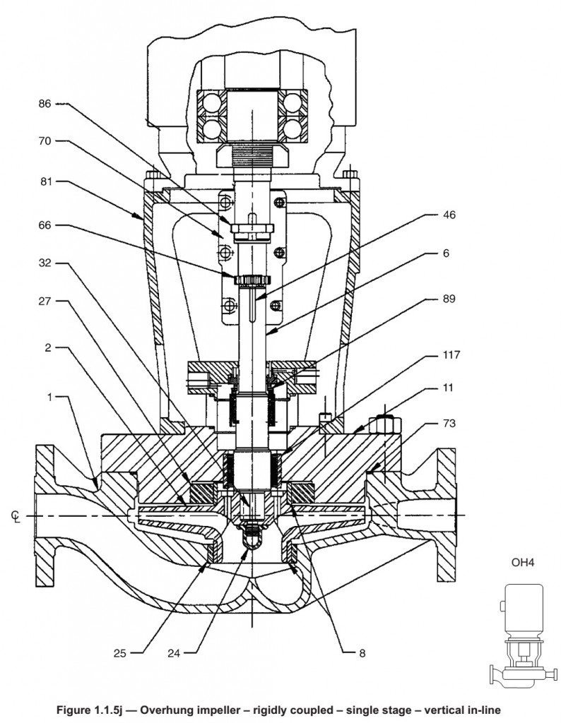
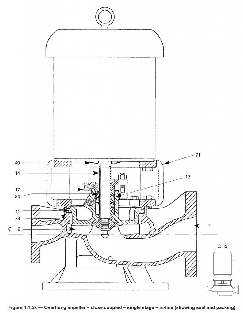
Vertical Inline Pumps Intro to Pumps
3. Steps to do Pump Piping. Step 1 : Collect the P&ID and the pump data sheet. Step 2 : Study the pump data sheet and collect the similar (capacity / head) pump dimensions / nozzle position. Step 3 : Analyse the location and the space provided in the unit plot plan w.r.t. suction and discharge line routing.

sewage ejector pump diagram Sump pump, Sewer pump, Sewage ejector pump
controller shall have its own individual pressure-sensing line. 4.30.2 The pressure-sensing line connection for each pump, including jockey pumps, shall be made between that pump's. discharge.

What Are the Three Types of Centrifugal Pumps? Flowmore Pumps
The Process Operator will "swing the spectacle blinds" on the Pump Suction Line and Pump Discharge Line "to the closed position." The spectacle blinds on the diagram are those Figure 8 shaped things that look like spectacles (eyeglasses). Take the time to locate the "spec blind" on the diagram. It is between the Suction Gate Valve and the.
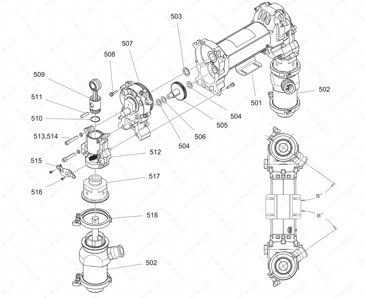
ToughTek F800e Pump Line Exploded Diagram Shop Online
Centrifugal Pump Diagram In this article, I am going to discuss the Centrifugal Pump Diagram. I will show you various centrifugal pumps with a schematic and cross-section to show you the different parts inside. I have covered the following centrifugal pump diagram with parts. Single stage open impeller pump Single stage closed impeller pump
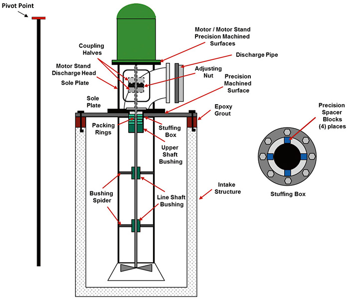
Steps to Successful Installation of Vertical Circulating Water Pumps
The single-line diagram is the blueprint for electrical system analysis. It is the first step in preparing a critical response plan, allowing you to become thoroughly familiar with the. Pump Fire Hydrant Pump 1 93000 Fire Pump r om 93000 31. 0 31.00 31.00 RYB3 630A MCCB set:504A 4x300.0 1x150.0 Main Distribution Panel
Types Of Pumps Plumbing Help
The completed reactance diagram is shown in Figure 5: TXLs should be j0.13724 (my correction) Figure 5 - Single line reactance circuit diagram (reactances shown on a per-unit basis) 7. Calculate Operating Conditions of the Motors If the motors are operating at 12 kV, this represents 12 kV/13.8 kV = 0.87 per-unit voltage.
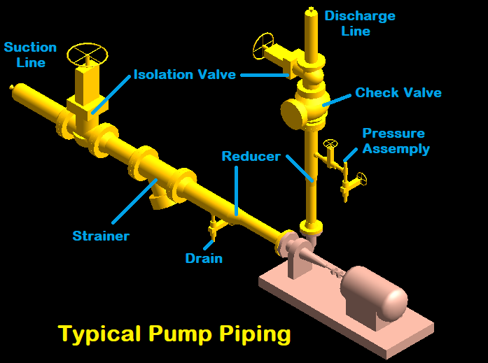
Pump Piping Design Considerations Make Piping Easy (2022)
Here they are. Study the figures below and review the list of general guidelines that follows. The recommended suction inlet size D should be (0.0744Q)0.5, where Q is the flow in gallons per minute (gpm). The minimum width W of the intake structure, per suction inlet, in the direction of flow, should be. 2D.
