Three Phase Electrical Wiring Installation in Home NEC & IEC
Below is a Wiring diagram of the distribution board , Single phase electric supply from electric pole and Energy meter to the main distribution board (Without RCD = Residual Current Devices).. Electrical Wiring Diagram of a 230V Single Phase, 63A Distribution Board (Consumer Unit) for AC Units, Lighting & 13A Radial Circuits.

Electric board connection on wall, Download the DWG file. Cadbull
Generally, Electric supply and service providers install a single phase energy meter when load is less than 7.5kW (10HP) in domestic areas (consumer unit for home). If the limit is exceeded, then it's recommended to install a 3-phase energy meter for consumer units. When load exceeds from 7.5 kW, then 3-phase electrical wiring is recommended.

Energy Meter Wiring Diagram Weaveked
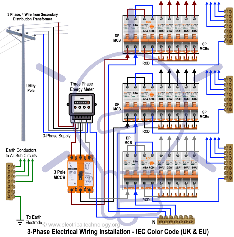
The wiring diagram of db board i shown below in which i shown the energy meter wiring and double pole mcb and single pole mcb circuit breakers connections. I also shown in earth wire connection which is very important in electrical technology. Now lets see the diagram of main board or main circuit breakers board.

wiring How to wire 1phase 3speed motor Electrical Engineering Stack Exchange
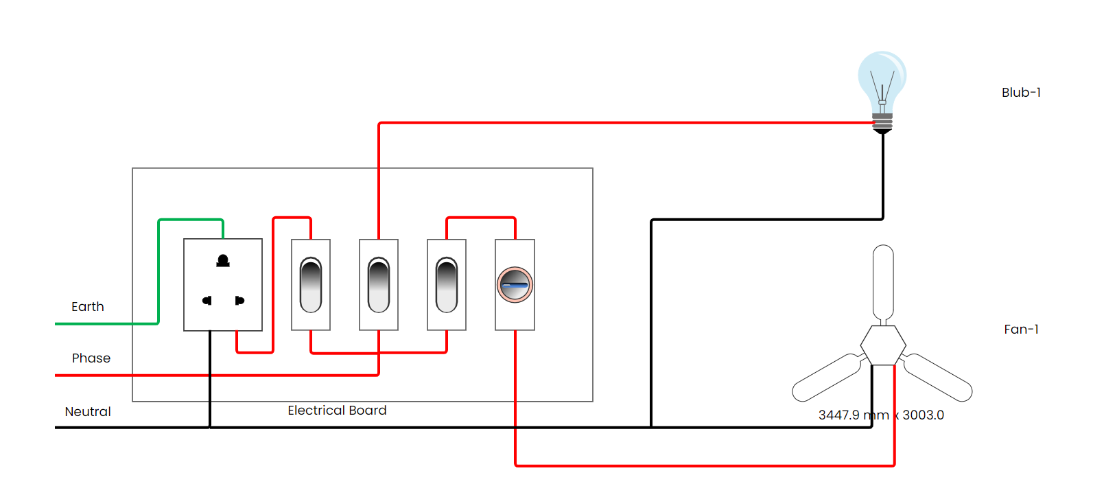
An electric switchboard is a device that directs electricity from one or more sources of power supply. In Switch Board, there are switch available to operate electrical appliances individually. Here Socket is also available to provide power to any other appliances that are not connected permanently to switch board. Electric Switch Board Uses?

raspberry pi Waves on raspberrypi camera feed, Ground loops? electrical interference
A distribution board (also known as Panel Board, breaker panel, or electric panel) is a component of an electricity supply system that divides an electrical power feed into subsidiary circuits while providing a protective fuse or circuit breaker for each circuit in a common enclosure. Distribution Board Uses?

Identification of Critical Lines in Power System Based on Optimal Load Shedding
A wiring diagram is a comprehensive diagram of each electrical circuit system showing all the connectors, wiring, terminal boards, signal connections (buses) between the devices and electrical or electronic components of the circuit. It also identifies the wires by wire numbers or colour coding. Wiring diagrams are necessary to troubleshoot and fix electrical or electronic circuits. Electrical.

Plc Panel Wiring Diagram Software Wiring Diagram
In the above diagram, I have shown the electrical cable with its size in mm in which are 6mm or 8mm, 4mm, 2.5mm, and 1.5mm electrical cables. Electrical Connectors. The connectors did their duty very well in Electrical wiring, this is the easy and compatible way of getting connections or joints in electrical wiring.
Switch Board Connection Diagram Sales USA, Save 48 jlcatj.gob.mx
An electrical panel board wiring diagram is a drawing that provides a visual representation of the connections between each component and the circuitry in a given system. These diagrams are often found in installation instructions that come with the electrical panel board, which makes them very useful for both installers and homeowners who are.

Pin on woodworking
In this video I show you how to wire a main electrical panel from start to finish. I show you how to wire a panel box neatly and very detailed to give a good.

Electronics and connection diagram for the PFC. Download Scientific Diagram
Distribution Board or DB is an electricity supply system or a common enclosure that distributes the electrical power feed into subcircuits. It includes isolator, RCCB (Residual current circuit breaker) or RCD (Residual-current device) devices, protective fuses or MCB's (Miniature Circuit Breaker) for each subcircuit, etc.

Electric Board Wiring Connection Diagram Wiring Diagram Wiring Board Electrical Board Electrical
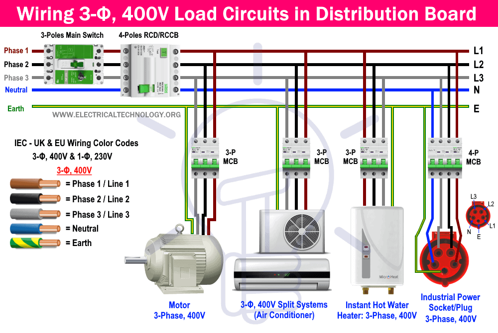
Grey= Phase 1 or Line1, Black= Line 2, Brown= Line 3, Blue = Neutral and Green= Earth Conductor. Below is the given wiring diagram of Single Phase Distribution Board with RCD in both NEC and IEC electrical wiring color codes. The same description and detailes can be used as mentioned for the above fig 1. Fig 2: Wiring Diagram of Single Phase.
220 3 Phase Generator Wiring Diagram
Electrical Distribution Board Wiring Diagram Power from the utility flows through a 2-pole MCB for overload protection, then an ELCB for safety. ELCB sends power to the house via single-pole MCBs, each guarding against overloads and shorts. The neutral bus bar connects all the circuits' neutral wires, and the earth bus bar connects all the.
3 Phase Diagram Electric Panel
222 Share 22K views 2 years ago Electrical & Circuit Diagram Complete Guide Free download EdrawMax or use it online to draw electrical wiring diagram easily https://bit.ly/34jFeDf 👉Find.
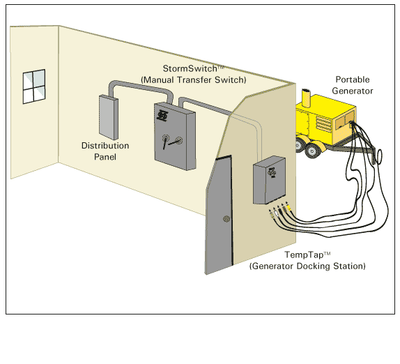
Generator Connection Diagram
The Spruce / Kevin Norris. One 15- to 20-circuit breaker box. $700 to $950 (labor not included) This overview describes how a professional electrician connects a residential electrical circuit breaker panel to the main service wires coming into the home, and to the individual branch circuits in your home. In almost every situation, this will be.

Electrical Extension Board Connection Diagram and Wiring ETechnoG
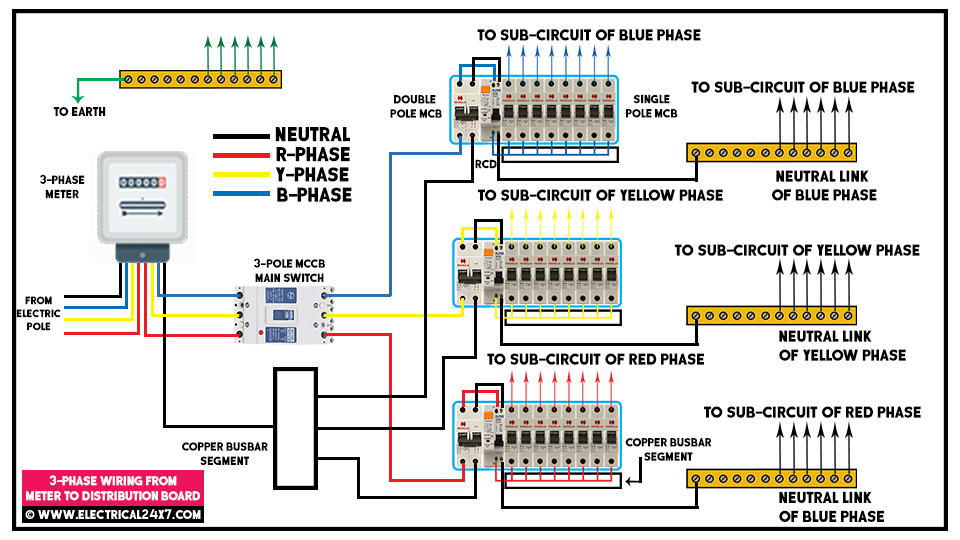
Below is three phase distribution board wiring diagram shown. The wiring connection is started from the main 600 A MCCB circuit breaker. The main 3 phase four wire supply enters the panel board. The 3 Phase Line 1, Line 2, and Line 3 (red, yellow, blue) are connecting to the line points of the MCCB circuit breaker.

Electrical Wiring In Iraq
In this board, balance load is distributed as phase wise. 2 - Connection Diagram of PDB: 3 - Components of EDB: PDB is the group of electrical parts where TPN MCCB is used for incoming and RCCB, ELCB are used for phase protection. Single phase MCB is used for lighting and power circuit. 1- Distribution Board Body: