
48v Lithium Ion Battery Charger Circuit Diagram
4 Simple Li-Ion Battery Charger Circuits - Using LM317, NE555, LM324. The following post explains a four simple yet a safe way of charging a Li-ion battery using ordinary ICs like LM317 and NE555 which can be easily constructed at home by any new hobbyist. Although Li-Ion batteries are vulnerable devices, these can be charged through simpler.
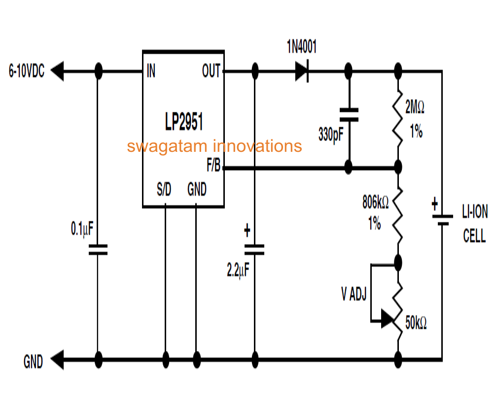
LiIon Battery Charger Circuit Using IC LP2951 Circuit Diagram Centre
51 thoughts on " Lithium-Ion Battery Circuitry Is Simple ". I wish there were a charger circuit as readily available as TP4056 boards that allowed 4.0v termination voltage, I'd replace.

How to Charge 25 nos LiIon Cells from a Single Circuit Circuit Diagram Centre
The word 'Ion' existing with the battery's name merely means that Lithium must never be encountered in its metallic form in the battery. The electrolyte collects lithium ions (Li+) on the graphite anode throughout the charging process.. Figure 4 depicts a Li-Ion charger circuit in accordance with the National Semiconductor IC LM 3622.

Email Empfohlen Studio arduino based battery management system Priester Automatisch Vene
Charging the battery forces the ions to move back across the electrolyte and embed themselves in the negative electrode ready for the next discharge cycle (Figure 1). Figure 1: In a Li-ion battery, lithium ions move from one intercalation compound to another while electrons flow around the circuit to power the load.
Lithium Battery Charger Circuit Diagram IOT Wiring Diagram
Figure 2: Typical application circuit for the MCP73827 Another easy way to charge a lithium battery is to use Linear Technology's LT3650, a DC-DC converter with integrated lithium-ion battery charger intelligence. A designer adds a few passive components to implement a complete lithium battery charging solution.

How to Make a Lithium Polymer Battery Charger Circuit
The circuit operates in a quite simple way. This lithium-ion battery charger circuit utilizes an LP2931 controller IC. The diode is working as a blocker / current blocker to prevent the current flow back into the IC when there is no voltage on the IC input. The yield voltage can be adjusted with a 50k potentiometer between 4.08V to 4.26V.

LithiumIon Charger Schematic Circuit Diagram
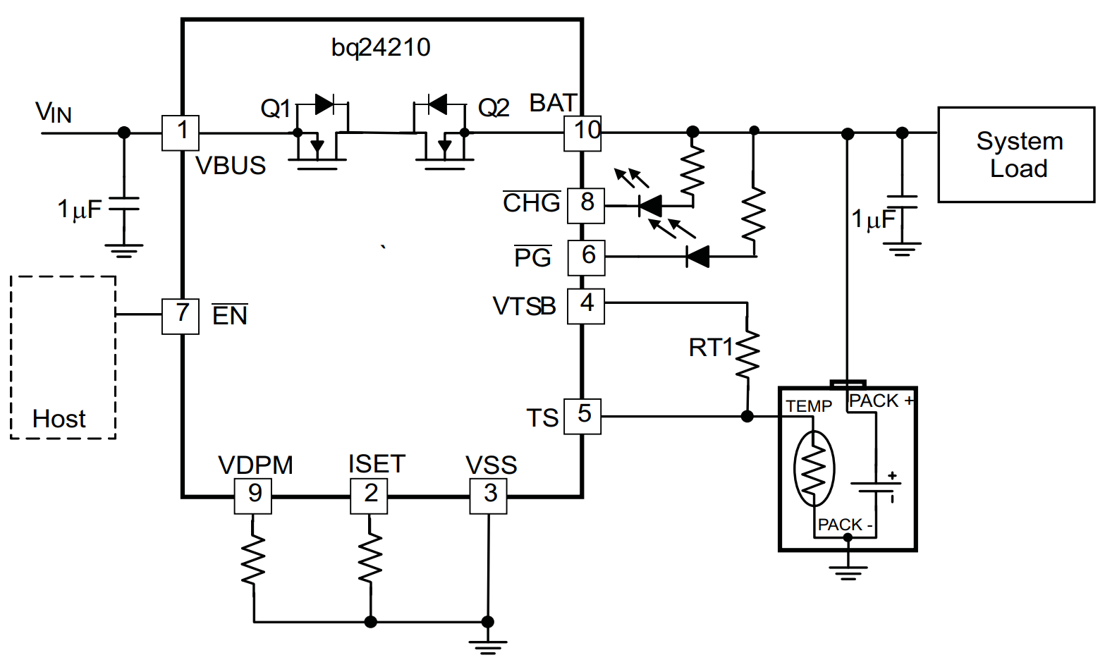
The final lithium ion battery charger circuit is the most advanced, and takes the advantages of the prior method, and removes the main con's. There are battery charging IC's made by Texas Instruments, Analog Devices, and Maxim that have what they call "Power Path" management.
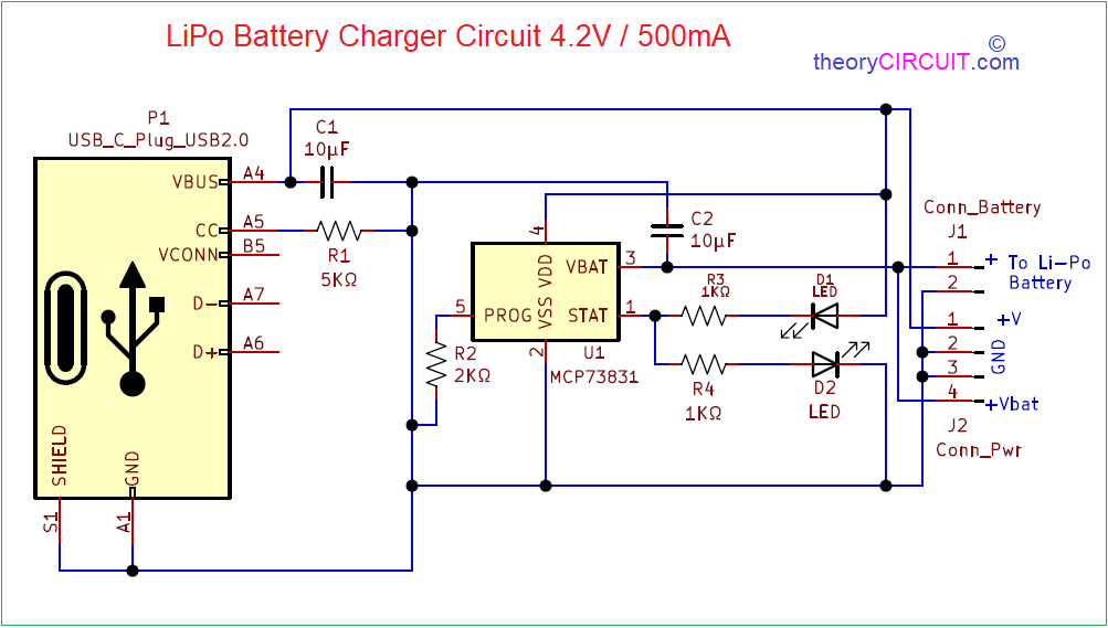
LiPo Battery Charger Circuit
Typically, PMICs charge LiPo and Lithium-Ion batteries using the CC-CV method. The battery gets charged with a constant current until the cell reaches its maximum voltage. From then on, the charger gradually decreases the charge current until the battery is fully charged. Modern charge ICs apply a few more steps to the process to increase.

LTC4002 2Cell 8.4V, 2A LiIon Battery Charger Circuit Collection Analog Devices
Materials needed. A microchip MCP73831, resistors, a 5VDC power source. Design Principle. You can use a standard 3.7-volt lithium-ion battery charger to charge a 3.7 V Li-Ion Cell up to 4.2V. The charger performs its function by increasing voltage from 0.25 V to 4.0 V in an hour at a 1 amp constant current charging rate.

LiIon Battery Charger Circuit Using IC 555
Step 1: Story. So Hey guys in today's article I am going to teach you how to make 3.7 Volt Lithium ion or LiPo battery charger circuit Lithium ion or LiPo batteries are very popular, especially with makers like.These batteries are also very sensible and dangerous. If you don't control the process of charging of such batteries, they will stop.
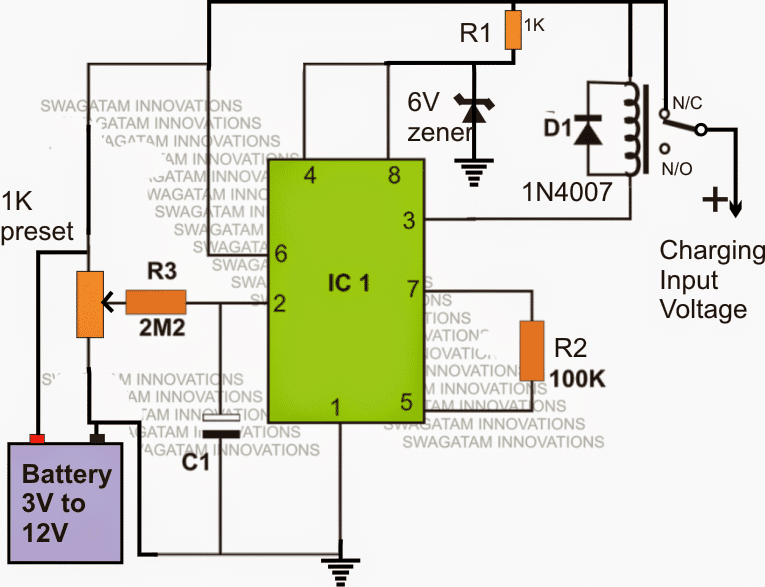
LiIon Battery Charger Using IC 555 Homemade Circuit Projects
Understanding the basics of charging and discharging circuits for lithium-ion battery cells is key to proper contacting system design as well as successful manufacturing and testing.
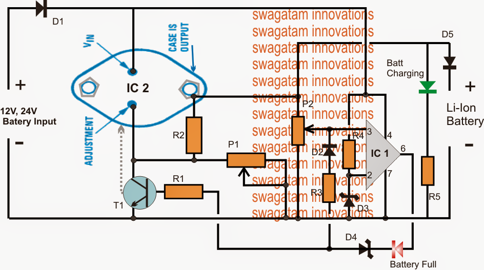
High Current 12V, 24V LiIon Battery Charger Circuit
Lithium-Ion Battery Charger Circuit . This post is about a tested sample circuit of a Lithium-Ion Battery charger that can be used to charge any 3.7V, 500mA Li-Ion battery using a 5V DC (USB, Solar Panel, DC Adapter) power supply. The circuit is designed using a microchip MCP73831/2 IC. MCP73831 is a highly advanced linear charge management.

LiIon Battery Charger Circuit
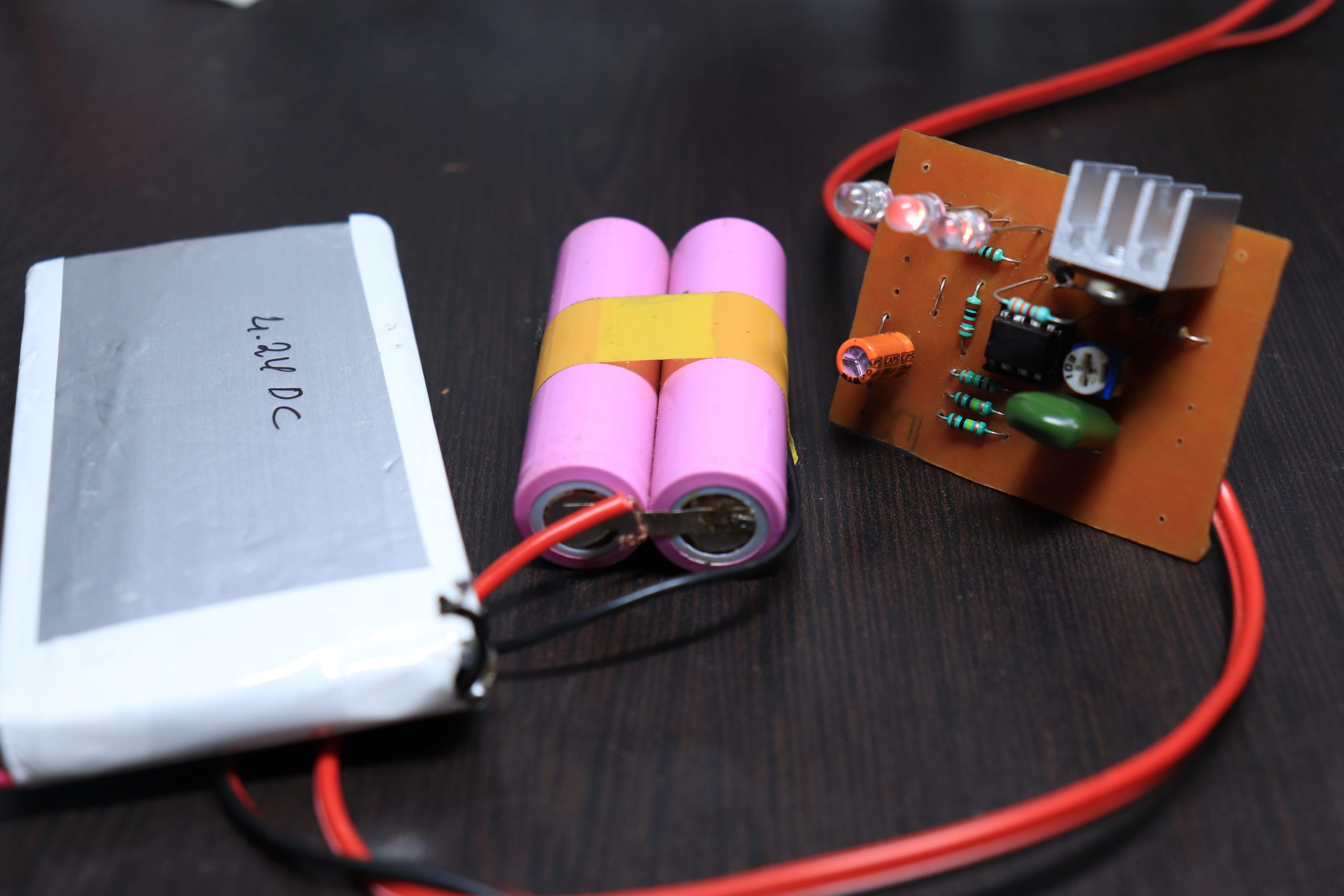
Step 8: Trial Run. Insert a discharged lithium-ion battery inside the charger, connect a 12 V DC input or a USB input. Charger should flash RED led indicating charging is in progress. After a while, once battery gets charged, charger should flash BLUE led.
Lithium Ion Battery Charger Circuit Load Sharing MicroType Engineering
Calibration: Step 1: Disconnect the battery to be charged. Step 2: Connect the DC power supply to the input. Step 3: Adjust the variable resistor till you get full charge voltage at the output terminal. (For 3.7V Li-ion output voltage will be 4.2V but here we will set it to 4.1V to increase the battery life).

3.7V LiIon Charger Module 1A with Battery Protection TP4056 in pakistan Electronics Hub
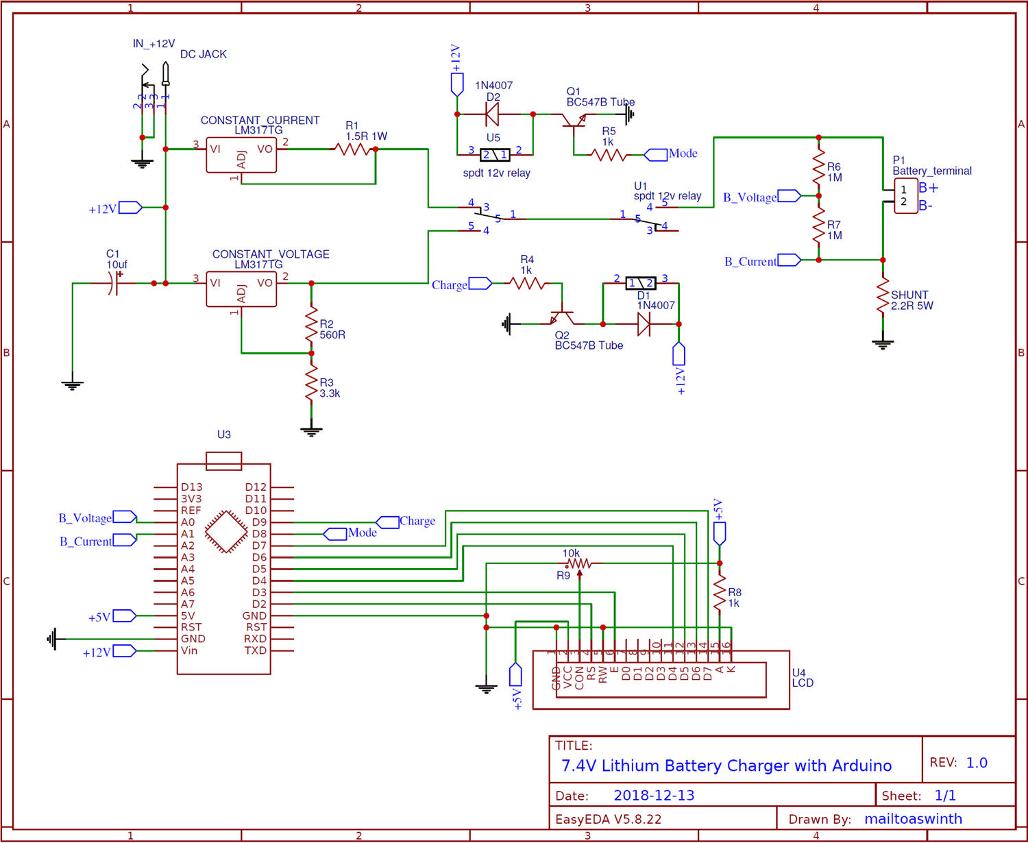
In this project we will build a Two Stage Battery charger (CC and CV) that could be used as to charge Lithium ion or lithium polymer batters. The battery charger circuit is designed for 7.4V lithium battery pack (two 18650 in Series) which I commonly use in most robotics project but the circuit can be easily modified to fit in lower or slightly.
Schematic Diy 18650 Battery Charger
The battery charger circuit is designed for 7.4V lithium battery pack (two 18650 in Series) which I commonly use in most robotics project but the circuit can be easily modified to fit in lower or slightly higher battery Packs like to build 3.7 lithium battery charger or 12v lithium ion battery Charger. As you might know there are ready made.
