on time delay timer circuit
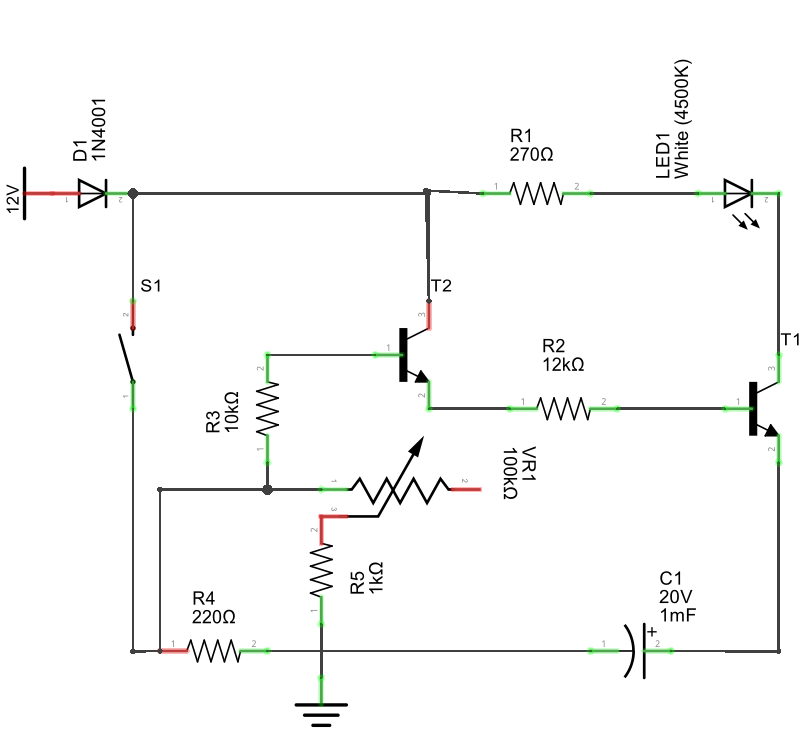
Simple Programmable Timer Circuit. Last Updated on January 2, 2024 by Swagatam 452 Comments. This programmable timer can be used for switching a load ON and OFF with two sets of time delays, which are programmable from 2 seconds to 24 hours independently. The delay timings are adjustable according to the users personal specs.
Simple Delay Timer Circuits Explained Homemade Circuit Projects
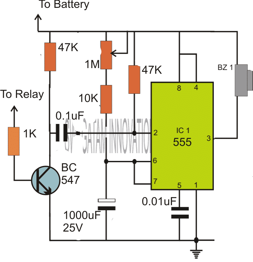
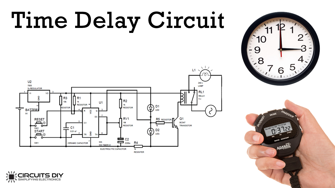
Timer Circuit with Relay Switching. If you are wondering how the above simple timer circuits could be used for triggering a high power load through relay switching, then the following diagram will help you to implement the same by attaching a simple relay stage with the shown designs: Parts List. All resistors are 1/4 watt 5%. R1, R4 = 4K7, R2.
How to Make an Industrial Delay Timer Circuit Homemade Circuit Projects
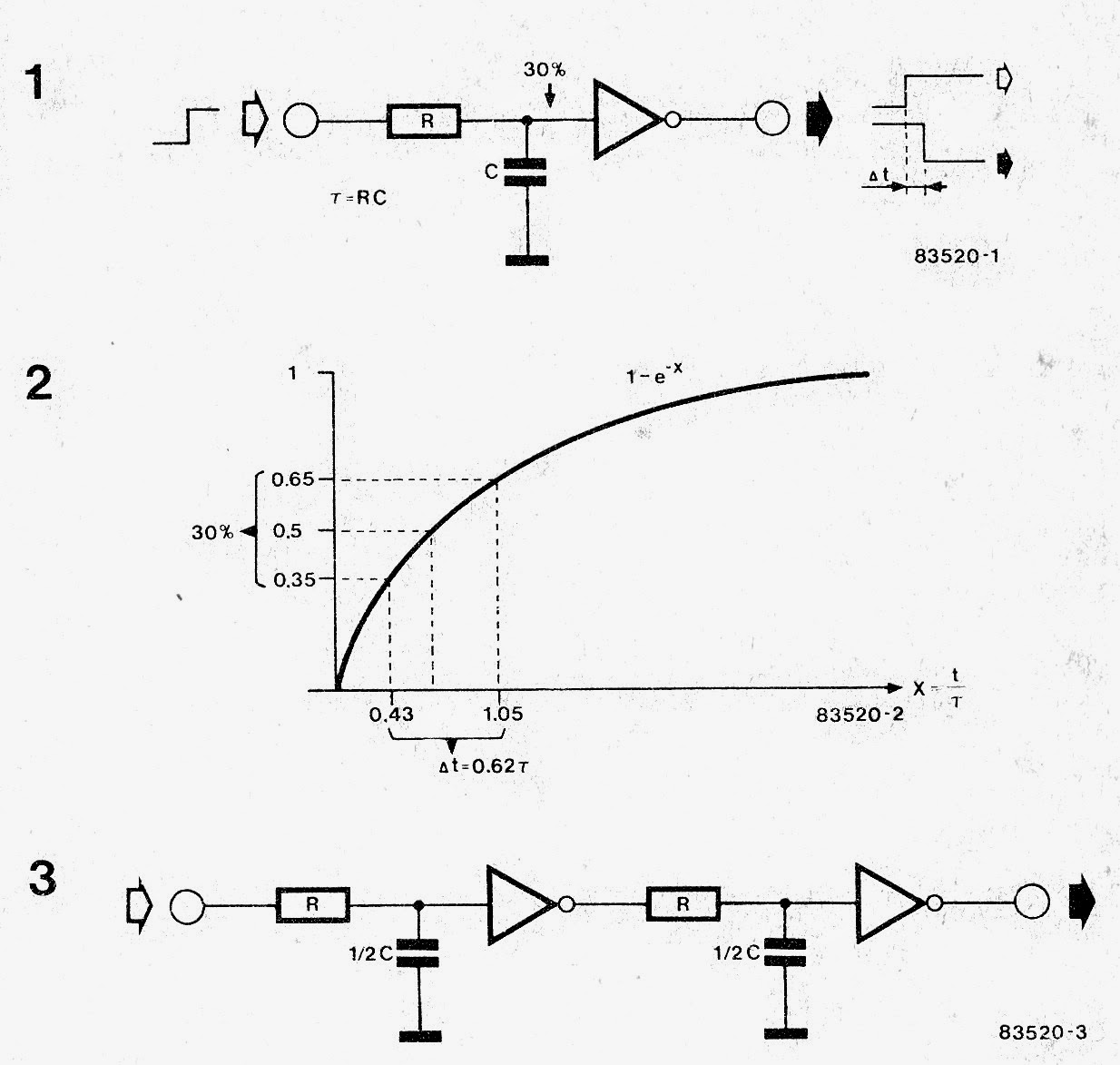
In astable mode, the output from the 555 timer is a continuous pulse waveform of a specific frequency that depends on the values of the two resistors (R A and R B) and capacitor (C) used in the circuit (fig 1) according to the equation below.Astable mode is closely related to monostable mode (discussed in step 2), you can see that the schematic is nearly the same.
How to make delay timer circuit ,diy easy delay circuit YouTube
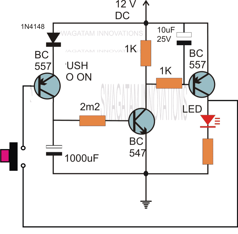
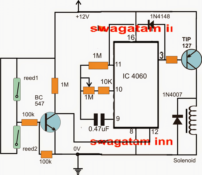
Simple Timer with Alarm. The next circuit is also designed using the CMOS IC CD4060, that includes a pulse generator and a counter. When power is switched on via S1, a reset voltage is given to the IC through C2. Simultaneously the IC built-in oscillator starts providing pulses to the counter. Following 213 clocks, the counter output (Q14) goes.

555 Timer Basics Astable Mode
Two Step Sequential Timer. The above circuit can be modified to produce a two step sequential delay generator. This circuit was requested by one of the avid readers of this blog, Mr.Marco. A simple delay OFF alarm circuit is shown in the following diagram. The circuit was requested by Dmats. The following circuit was requested by Fastshack3

TIMER CIRCUIT how to make simple timer circuit using one transistor
The 555 timer IC is a very cheap, popular and useful precision timing device which can act as either a simple timer to generate single pulses or long time delays, or as a relaxation oscillator producing a string of stabilised waveforms of varying duty cycles from 50 to 100%.. This 555 timer circuit will remain in either state indefinitely.

DIY Arduino Simple LED Timer Circuit 3 Steps Instructables
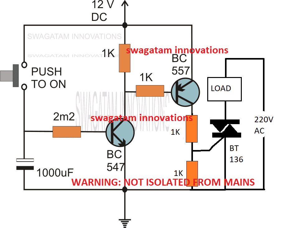
A timer switch or timer circuit is a timer to control any electronic switches or circuits by a timing mechanism. Here, the timer is a very simple circuit, working by using just one or a pair of transistors. this circuit serves its purpose of time delays operation of a device. The timer circuit is made with a number of different schematics which.
Simple Timer Circuits using IC 555 Adjustable from 1 to 10 minutes
555 Timer Circuits - List. As discussed, let's begin our first section - 555 timer circuits - which lists practical and simple 555 timer circuits which helps a student to learn fundamentals about building a 555 IC based circuit. 1. 7-Segment Counter Circuit.
Simple Delay Timer Circuit How to Make and Calculate Schematics World
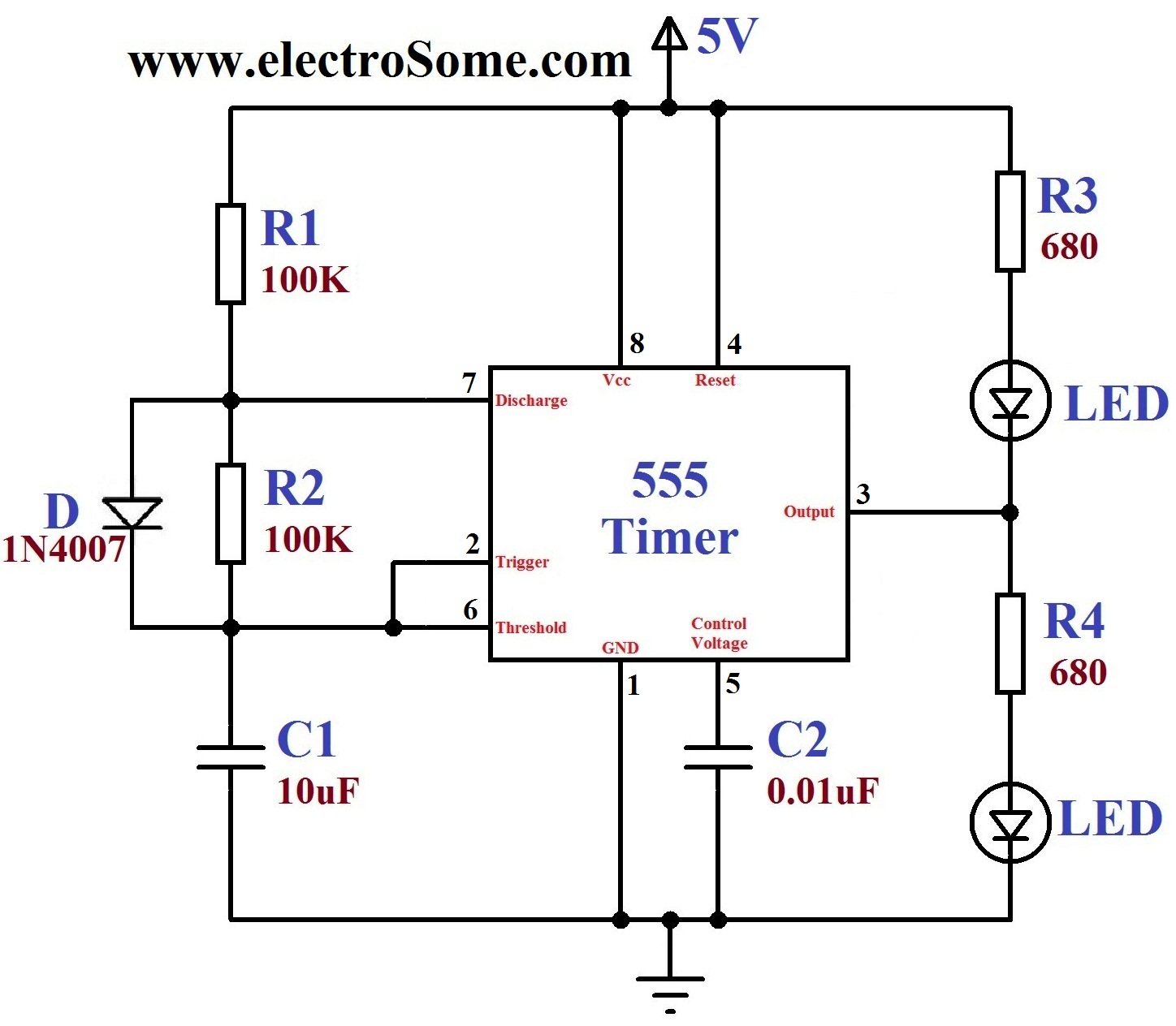
A 555 timer can give out only 100 to 200 mA in total. Check your chip's datasheet for the exact value. This pin resets the whole circuit. It's an "inverted" pin, which means it resets when the pin goes low. This means the pin must be high normally so that the chip isn't in a "reset" state.
Simple Time Delay Circuit using 555 Timer
Step 3: Testing and Tuning. Its now time to test the circuit and add the extras. Add a button connecting the positive rail to the signal in line and connect an LED and a resistor to the signal out line. Apply power and push the button, if it lights up for a short time then fades out, the circuit is working properly and you can now add the relay.
Simple 5 to 20 Minute Delay Timer Circuit Circuit Diagram Centre
Here i am going to explain different ways of building adjustable timer circuits. However, these methods are cost ineffective.Three circuits are explained here are 1)Simple adjustable timer using 555 IC,2)A cyclic on/off timer using 555 IC,3)Adjustable timer using arduino. (40+ Simple 555 Timer Circuits & Projects)
Simple long duration timer
555 timers are an incredibly popular IC that is useful for timers, switches, LED blinking, and more, using a simple analog circuit and no programming. In th.
Simple 2 minute Timer Circuit for your DIY Digital Lab
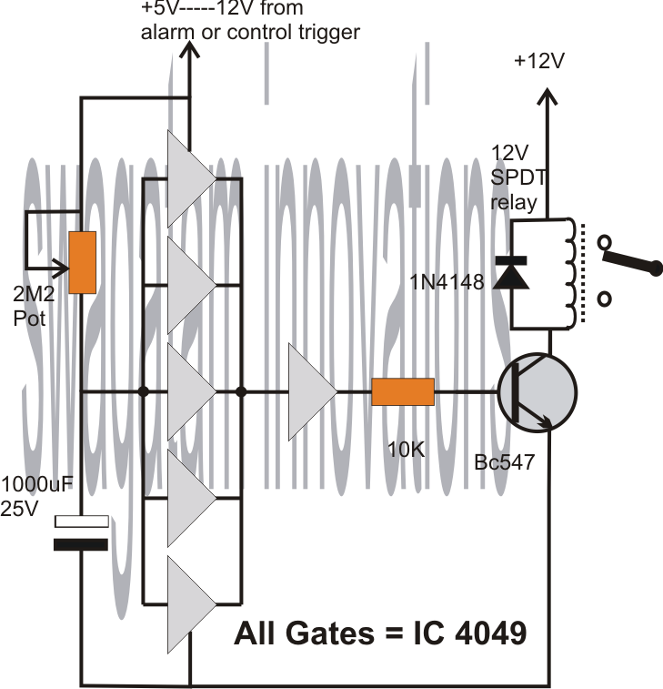
So to build 1 minute (60 seconds) timer we need resistor of value 55k ohm and capacitor of 1000uF: 1.1*55k*1000uF. (1.1*55*1000*1000)/1000000 = 60.5 ~ 60 seconds. A variable resistor of 1M is used here and set on 55k ohm (measured by multimeter). We can easily calculate the resistor value for 5 minute, 10 minute and 15 minute timer circuit:
Simple Delay Timer Circuits Explained Homemade Circuit Projects
Simple 555 Timer Circuits & Projects. March 18, 2017. By Anusha. 555 timer is an industrial standard IC existing from early days of IC. Its name is derived from three 5K ohm resistors ,connected in series used in it.The timer IC can produce required waveform accurately. 555 timer was first introduced by signetics corporation in 1971 as SE555/NE555.
Simple timer circuit using Ic 555
The PWM 555 Circuit is known as an improved 555 oscillator. This is because it makes use of a couple of extra components to improve the output signal that the most common astable multivibrator circuit would give. It uses R1 and C1 to control the frequency of the signal. And you can modify the duty cycle with RV1.
555 timer circuit Page 4 Other Circuits Next.gr
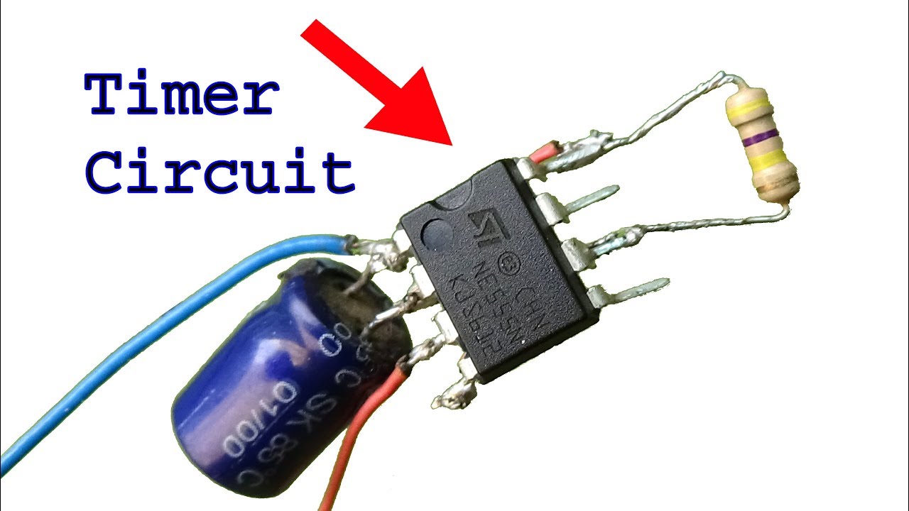
in this video, I will show you how to make a time circuit using a transistorBuy Electronic Component From Here:- https://www.electronicspices.com/If u really.