480V 3 Phase To 120 240V Transformer Wiring Diagram EdenBengals
The 24V Transformer wiring diagram usually contains the following information: the input voltage, output voltage, current rating, percentage load, and protection features. This information is important in determining the proper way to wire a transformer.
24 Volt Transformer Wiring Diagram Cadician's Blog
A 24V transformer wiring diagram shows the connections made between several components. It includes the primary and secondary windings of the transformer, as well as connections to other electrical devices. The diagram also includes the type of wiring used to connect the various components, such as single-phase or three-phase wiring.
240v Wiring Colors
Step 7. Twist the bare ends of the wires together using your wire pliers. Cover the connections with a plastic wire nut. Turn on the electrical power to the device. A 24 VAC (volt alternating current) transformer is a step-down type of transformer. The device typically converts 120 VAC to a lower voltage for use in push buttons.
24v Transformer Wiring Diagram Wiring Flow Schema
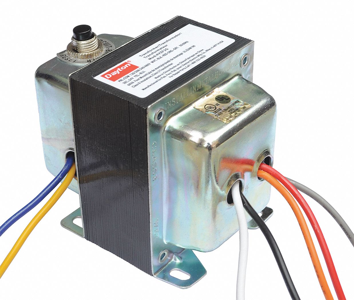
Once you know which two wires have the voltage for the tap you want, simply connect one power wire to the wire on our transformer with the voltage tap you want, and the other power wire to the wire on our transformer labeled "Comm". Then separately insulate each of the unused wires. It's that easy! For the sake of clarity let's do some examples.

Control Transformer 40VA, Primary 120, 208, 240V Secondary 24V, HVAC
A properly installed transformer can ensure a safe and efficient electricity supply for many years to come. Open Coil Machine Tool Control Transformer. Universal Transformer 120 208 240v To 24v 40 Watt. Wiring Of Control Power Transformer For Motor Circuits Eep. Furnace Transformer What It Is And How To Fix Common Issues
240V 24V Transformer Wiring Diagram For Your Needs
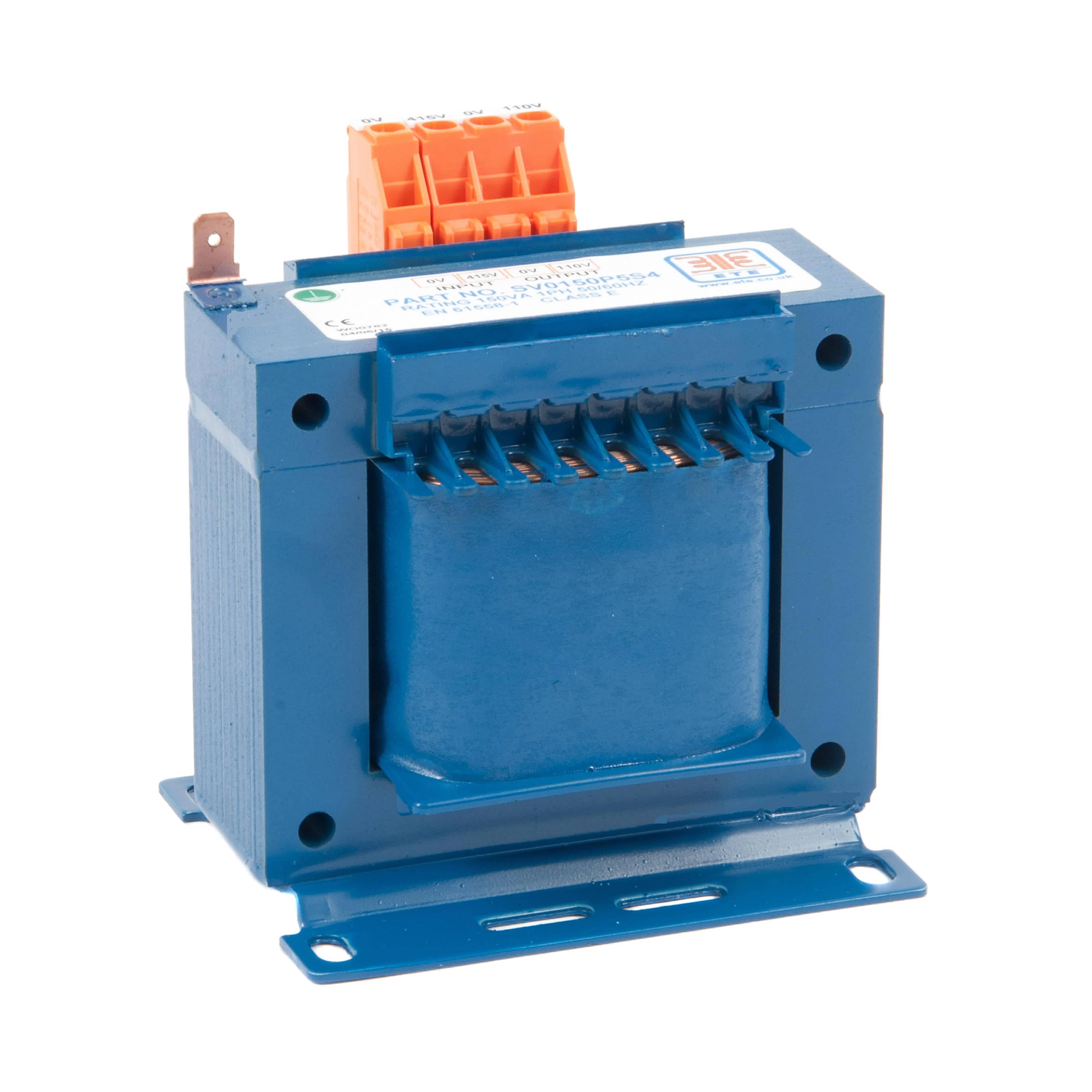
TA Series Open Core & Coil Wiring Diagrams Group A Group B Group C X2 X1 H1 H3 H2 H4 24V H1 H2 240V 120V H3 H4 H1 H3 H4H2 X2 X1 120V 115 110 H1 H3 H2 H4 H1 H2 480V 460 440 H3 H4 H1 H3 H4H2 240V 230 220 X1. Acme Electric - TA & TB Series Control Transformers - Wiring Diagrams Author: Galco Industrial Electronics
Industrial Control Transformer Wiring Diagram Download Wiring Diagram
The 240v 24v transformer wiring diagram is a tool used to explain how this type of transformer works and how it is wired. How 240v 24v Transformers Work 240v 24v transformers are used to convert a higher voltage to a lower voltage, or vice versa.

24 Volt Wiring Diagram
If so, you've come to the right place. In this article, we will discuss the basics of a 24v transformer wiring diagram and why it's an essential component in any modern electrical setup.First, let's start with the basics. A transformer is a device that converts… Read More ». 100va Transformer Primary 120v 208v 240v 480v Volt 24v Secondary.

24V Transformer 120 To 24 Volt Transformer Wiring Diagram Database
The basic elements of a 120/240 transformer wiring diagram include the following: single-phase input lines, three-phase output lines, three-phase secondary lines, and a three-phase internal circuit breaker. The single-phase input lines connect the primary side of the transformer to the power source. The three-phase output lines connect the.
24vac transformer wiring diagram
The first is the 240-24 volt transformer wiring diagram and the second is the 240-240 volt transformer wiring diagram. Each type of wiring diagram will produce different results depending on how you wire the circuit. It is important to understand how to properly use these diagrams when attempting to hook up a transformer.

24 V Transformer Wiring
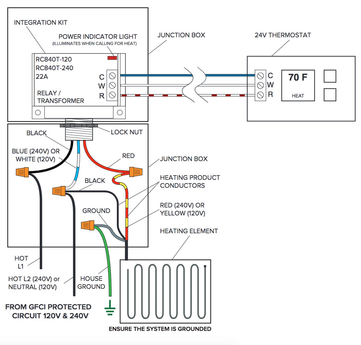
12 volts 24 volts Important: Check secondary voltage before connecting to controls. It should be from 24 to 28 volts. Check this wiring diagram against the wiring diagram supplied with the transformer. The color of the wires may be different.

240 To 24v Transformer Wiring Diagram
24v Transformer Wiring Diagrams are a combination of circuit schematics and graphical symbols that represent the connections between two or more parts in an electrical circuit. It serves as a roadmap to the installer and helps him correctly install, diagnose and troubleshoot the entire system.
Electrical Transformer Circuit Diagram
1.5K 301K views 11 years ago http://www.fixmyownac.com - Learn how to wire a transformer. Visit our website to learn more about fixing your own air conditioning unit, read articles and wiring.
[DIAGRAM] Honeywell 24v Relay Transformer Wiring Diagrams MYDIAGRAM
In the intricate realm of electrical systems, the 240v 24v transformer wiring diagram serves as the mystical guide that unravels the complexities. Aglow with interconnected symbols and lines, this enigmatic diagram beckons us to venture into the realm of voltage conversion. As we delve deeper, we begin to decipher the secret language that brings the 240 volts down to 24 volts, unveiling the.
Oberfläche Beschleunigung Jurassic Park transformator 240v 24v Extrakt
When it comes to wiring a transformer, the 240v 24v transformer wiring diagram is a valuable tool. It is important to understand the different components and how they are connected. This diagram will help you to troubleshoot any problems that you may encounter during the installation process. Components of the 240v 24v Transformer Wiring Diagram […]

24v Transformer Wiring Diagram Wiring Draw
If you have any questions regarding these wiring diagrams or are having any difficulty correctly installing our transformers, please contact HPS customer service or technical support in the U.S. at 1-866-705-4684 or in Canada at 1-888-798-8882. HPS Imperator tm Industrial Control Transformer Wiring Diagrams Issue Date: October 2007 rev4 Page 1 of 9
